Optimizing Inner-Tube Lip Geometry for Soft-Formation Coring
Introduction: Why Soft Ground Destroys Core Recovery
Few drilling frustrations escalate faster than poor recovery in soft ground.
The borehole advances. Meterage increases. Consumables continue to burn. Yet the sample box arrives at surface incomplete, washed, fragmented, or unusable.
For geologists, poor sample integrity compromises confidence in lithological interpretation. For drilling contractors, low recovery percentages increase non-productive time, trigger costly re-drilling, and damage cost-per-meter performance.
In Soft-Formation Coring, failure rarely begins at the rig.
It begins at the bit face.
Broken formations, weathered intervals, clay-rich zones, and friable ground respond differently to drilling stress. Mechanical aggression that works in competent rock often destroys recoverable material in weak formations.
One of the most overlooked variables is Inner-Tube Lip Geometry.
Millimetres separating the inner-tube lip from the cutting face determine whether soft core is protected, washed away, or fragmented during drilling.
In many cases, recovery problems attributed to geology are mechanical problems instead.
Understanding the Mechanics of Soft-Formation Coring
Why Soft Ground Behaves Differently
Competent formations fracture predictably.
Friable and unconsolidated intervals do not.
Soft ground often includes:
- Weathered rock
- Broken ground
- Clay-rich zones
- Altered formations
- Highly fractured intervals
- Weak sedimentary material
Instead of maintaining structural integrity during drilling, these materials deform, slough, fragment, or wash away under hydraulic loading.
The challenge becomes stabilization.
Without mechanical support near the bit face, soft material disintegrates before entering the recovery system.
Conventional drilling logic frequently fails because operators compensate with higher flow rates, increased penetration, or aggressive drilling parameters.
This often worsens sample destruction.
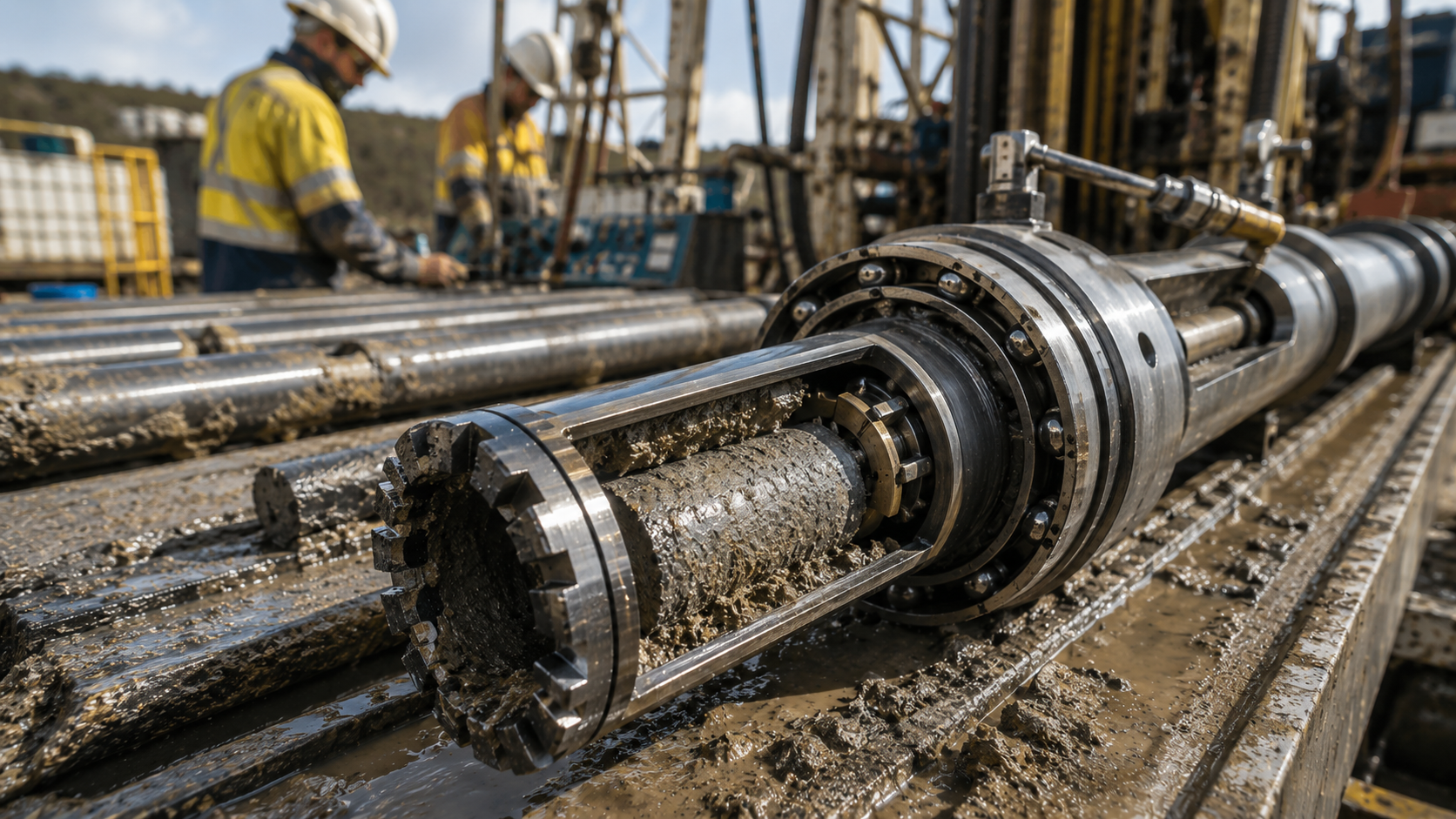
The Role of Inner-Tube Lip Geometry
The distance between the inner-tube lip and the bit face governs recovery performance.
In practical terms, the lip acts as a stabilizing interface.
Its purpose is to support fragile core immediately after cutting and guide material into the inner tube with minimal disturbance.
This is why millimetres matter.
Minor dimensional changes influence:
- Core support
- Fluid turbulence
- Sample washing
- Fragment retention
- Borehole stability
- Hydraulic disturbance
When the Lip Is Too Close
If the inner-tube lip sits excessively close to the bit face, the system becomes mechanically restrictive.
Consequences may include:
- Core blockage
- Increased friction
- Core grinding
- Excessive fragmentation
- Reduced penetration efficiency
Weak formations may compress or deform under excessive contact pressure.
Instead of protecting recovery, the lip becomes destructive.
When the Lip Is Too Far
Excessive clearance produces a different problem.
A larger distance exposes freshly cut material to turbulent drilling fluid.
This creates instability between the cutting zone and recovery system.
Results commonly include:
- Core Washing
- Sample erosion
- Increased fines generation
- Recovery loss
- Fragment dispersion
Fragile material becomes hydraulically unstable before entering the tube.
The result is incomplete or unreliable recovery.
Correct Lip Geometry
Correct Inner-Tube Lip Geometry minimizes unsupported travel distance.
The objective is stable core transfer.
Proper calibration supports:
- Immediate sample capture
- Reduced hydraulic disturbance
- Improved core continuity
- Better retention in friable formations
- Increased Core Recovery
The mechanical goal is simple:
Cut, support, stabilize, retain.
Bit Face Hydraulics and Core Washing
How Fluid Dynamics Destroy Core Recovery
Hydraulics often destroy more core than drilling mechanics.
Fluid exiting the bit face creates localized velocity zones around freshly cut material.
When flow becomes unstable, Core Washing occurs.
Instead of entering the tube intact, weak formations erode or disperse.
Common causes include:
- Excessive flow rate
- Turbulent fluid velocity
- Incorrect lip spacing
- Poor hydraulic discipline
- Over-aggressive flushing
Soft formations are particularly vulnerable because their cohesion is already limited.
Fine material breaks down rapidly.
The outcome appears as:
- Washed intervals
- Mud-contaminated sample
- Excessive fines
- Low recovery percentage
Managing Hydraulic Stability
Successful Bit Face Hydraulics depend on minimizing disturbance.
Operators should aim for controlled flow conditions that evacuate cuttings while preserving sample integrity.
Best practice includes:
- Controlled fluid velocity
- Stable circulation discipline
- Correct lip calibration
- Reduced turbulence near fragile intervals
- Consistent drilling parameters
Higher flow rates do not necessarily improve recovery.
In friable ground, they often reduce it.
The Hidden Mechanical Failures Behind Poor Recovery
Bearing Assemblies
Stable tube rotation matters.
Worn Bearing Assemblies introduce vibration and instability into the wireline system.
Mechanical instability produces:
- Tube oscillation
- Sample disturbance
- Increased fragmentation
- Irregular core entry
Minor bearing wear often creates disproportionately large recovery losses.
Mechanical smoothness matters.
Fluid Shut-Off Valves
Fluid Shut-Off Valves control fluid movement during coring.
Improper valve performance increases washing risk by allowing uncontrolled fluid intrusion into the sample zone.
Warning indicators include:
- Excessive slurry contamination
- Washed core surfaces
- Inconsistent returns
- Poor retention performance
Valve maintenance is often overlooked until recovery deteriorates.
Core Lifters
Core Lifters govern retention reliability.
A worn lifter struggles to grip fragile material effectively during retrieval.
Common consequences include:
- Partial sample loss
- Fragment slippage
- Reduced recovery continuity
- Increased breakage
Routine inspection becomes critical in soft ground.
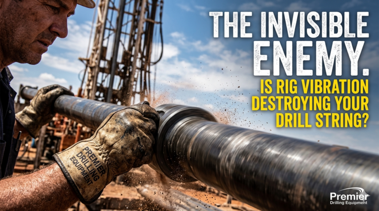
Drill String Vibration
Drill string instability transfers directly to the sample.
Vibration amplifies disturbance near the bit face, increasing fragmentation and erosion.
Contributing factors include:
- Poor parameter control
- Imbalanced tooling
- Worn components
- Aggressive drilling behaviour
Stable mechanics improve recovery.
Unstable mechanics destroy it.
How to Identify Recovery Problems Before the Sample Is Lost
Poor recovery usually announces itself before catastrophic sample loss occurs.
Operators should monitor for early warning indicators.
Recovery Diagnostic Checklist
Watch for:
- Fragmented core appearing excessively broken or discontinuous
- Excessive fines indicating erosion or washing
- Washed intervals showing material loss between recoverable sections
- Reduced recovery percentage despite consistent geology
- Tube vibration or unstable mechanical feel during drilling
- Muddy or over-flushed sample indicating hydraulic disruption
- Excessive fluid velocity causing instability at the bit face
- Repeated core lifter wear reducing retention consistency
- Inconsistent penetration rate suggesting instability at the cutting interface
The earlier problems are identified, the cheaper they become to correct.
Ignoring them usually results in re-drilling.
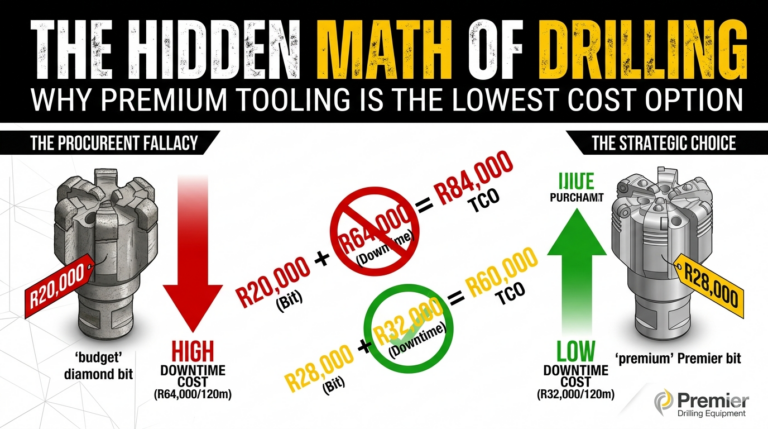
The Economics of Mechanical Precision vs Re-Drilling
Poor recovery damages drilling economics faster than many crews anticipate.
Consider a simplified comparison.
| Performance Area | Poor Geometry Setup | Calibrated Geometry |
| Recovery percentage | Low | High |
| Geologist confidence | Reduced | Improved |
| Re-drilling requirement | Frequent | Minimal |
| Crew downtime | Elevated | Reduced |
| Consumable waste | High | Controlled |
| Meter productivity | Reduced | Improved |
| Sampling confidence | Poor | Reliable |
Under a poor setup scenario, fragmented recovery often forces repeat drilling or creates uncertainty in geological interpretation.
Crews spend more time correcting preventable problems.
In contrast, properly maintained Wireline Core Barrels with calibrated lip geometry deliver better recovery continuity and lower overall drilling cost.
Precision reduces waste.
Prevention Strategy: Building a Soft-Formation Coring Program
Calibration Discipline
Inspection routines should include millimetre-scale verification of Inner-Tube Lip Geometry.
Small deviations create major performance differences.
Calibration should become standard practice.
Hydraulic Management
Fluid behaviour must remain controlled.
Crews should regulate:
- Flow rate
- Circulation stability
- Turbulence
- Cuttings evacuation
Hydraulics should support recovery, not disrupt it.
Maintenance Discipline
Preventative inspection matters.
Routine maintenance should prioritize:
- Bearing Assemblies
- Fluid Shut-Off Valves
- Core Lifters
- Tube condition
- Wear monitoring
Soft-ground coring magnifies mechanical imperfections.
Data-Led Recovery Optimization
Recovery trends should be monitored continuously.
Key indicators include:
- Recovery percentage
- Fragmentation frequency
- Sample washing
- Tool wear
- Penetration consistency
Good recovery is measurable.
Poor recovery leaves warning signs.
Conclusion
Successful Soft-Formation Coring depends on precision.
Weak formations cannot tolerate uncontrolled hydraulics, poor calibration, or unstable mechanics.
The distance between the bit face and Inner-Tube Lip Geometry directly affects sample stability, fluid behaviour, and Core Recovery performance.
When combined with disciplined maintenance of Wireline Core Barrels, properly functioning Bearing Assemblies, reliable Fluid Shut-Off Valves, and maintained Core Lifters, operators improve recovery while reducing re-drilling and downtime.
In soft ground, millimetres determine outcomes.
Mechanical precision is not optional.
It is the difference between reliable geological data and an expensive recovery problem.